Computed tomography
We engage in problems of the industry concerning defect detection and quality assurance of materials and components using industrial computed tomography (CT).

Equipment and Tools
CT-Equipment and Software ToolsPublications
journal publications and conference contributionsTeam
our researchersFields of Application
Computed tomography is the only method with which it is possible to look inside materials and components without influencing their further use or changing their shape - nondestructively. The inner structures are reconstructed and virtually illustrated without damaging the samples.
The CT-Methodology
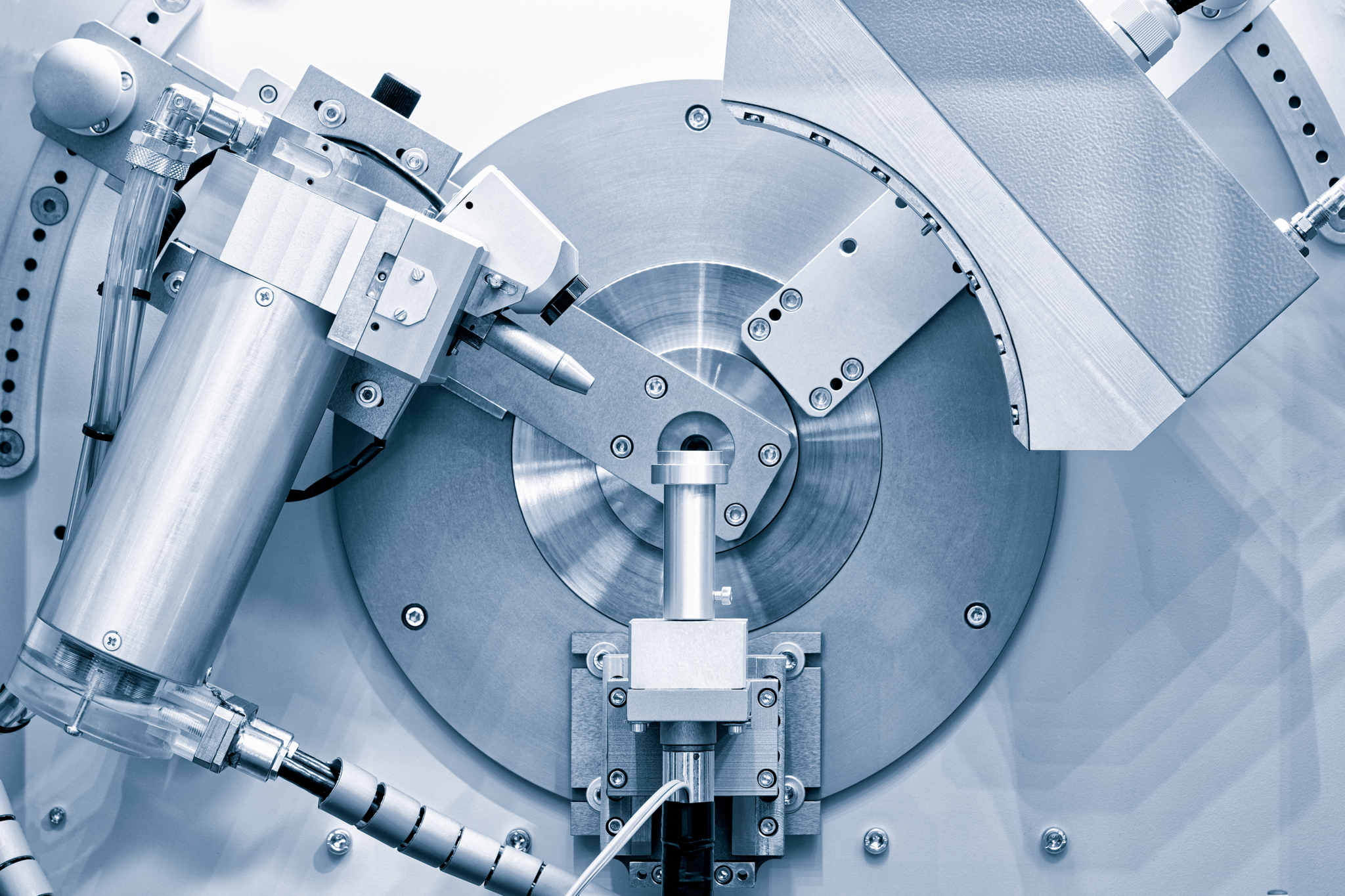
In principle, a 3D computed tomography scanner consists of 3 components: the X-ray source, a rotary table on which the sample is mounted and a digital detector. The X-ray source emits an X-ray beam which spreads cone-shaped. When the X-ray beam penetrates the sample, the intensity is attenuated depending on the sample thickness, the density and atomic number of the material. The digital detector converts the X-ray intensity into a digital projection image. To get a 3D image of a sample, a full rotation of the sample within the X-ray beam is essential, so the rotary table stops at uniform angle steps for taking another projection image. Depending on the required quality of the 3D dataset and the sample, 1000-2000 projections are needed to create a 3D dataset.
To analyse a 3D dataset (also called volume data, with a single data value at a position called voxel), special software is needed. This software splits the volume data into Axial, Frontal and Sagittal slices to display the results on screen, similar to a metallographic preparation. These three slices are orientated to the global coordinate system of the 3D dataset. Axial means a slice in X-Y, Frontal in X-Z and Sagittal in Z-Y direction. By different rendering-algorithms, the software can also display a 3D image of the measured sample. The different grey values correspond to the material density, where high density leads to a bright representation and low density to a dark one.
I'll help you choose your study program.